|
Model 350A overwrapping machine is developed
on basis of model BT-2000A and is applicable
for a little big sized box such as mobile
box ,cigarette box with 10 pack cigarette
box etc. The difference from BT-2000 series
and BT-350A is that BT-350A turret is only
four part but the BT-2000 series turret
eight part.
Features:
1/Functions: Anti-false and moisture-proof
2/Adjustable to different sizes
3/Speed Adjuster, temp. adjuster
4/ hopper feeding, Tear-tape device.
Main specification��
|
Model
|
BT-350A
|
|
Production capacity
|
10-25(packs/min)
|
|
Package size
|
Max film width<340mm
|
|
Voltage supply
|
220V 50Hz single phase
|
|
��
|
380V 60hz three phase by special
order
|
|
Electric heating
|
0.75KW
|
|
Power consume
|
4KW
|
|
Overall size
|
2800X950X1600MM(LXWXH)
|
|
N.weight
|
1000KG
|
BT-350 Cellophane Paper(Film) Box-type
Tridimensional Packing Machine
��
Operation Instruction
Table of Contents
1.
Introduction
2.
Outside drawing of the
machine
3.
Working principle and packing
flow diagram
4.
Packing dimensions
5.
Main technical parameters
6.
Packing materials
7.
Performance and structural
features
8.
Installation
9.
Notice
10.
Operation specification
11.
Debug rules
12.
Troubles and shooting
13.
Electrical schematic diagram
14.
Detailed list of main
electrical components
15.
Packing list
1. Introduction
This machine is a universal
equipment for tridimensional packing the hard
paper pack boxes or pack articles of various
specifications by using cellophane paper or OPP
film. It is a new innovation designed by our
company based on domestic and foreign advanced
technologies. It has a main body of mechanical
linkage and uses stepless variable-frequency
speed-governing and self-operated electrical
accessories. It is compact, beautiful and
convenient for operation and maintenance with
small volume, light weight and a high level of
automation.
This machine is widely
applicable to the packing of the small-sized
boxed articles, e.g. medicine, health protecting
products, nutriment, food, cosmetics,
stationery, VCD, magnetic tape, playing cards,
and cigarette, etc. It has anti-false and
moisture-proof functions and the added value,
grade and decoration quality of the products. It
is an ideal box-type tridimensional packing
equipment.
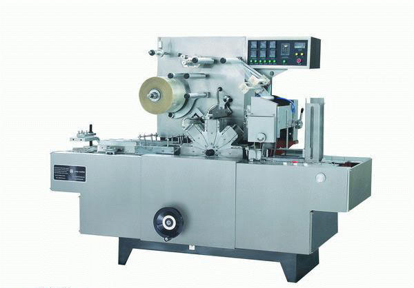
2.
Outside drawing of the machine(See Figure 1)
3.
Working principle and packing flow diagram
BT-350A Cellophane
Paper(Film) Box-type Tridimensional Packing
Machine supplies the pack articles by using
storage case and conveying belt, and performs
packing by using the mechanisms of paper(film)
feeding, paper(film) cutting, folding, wrapping,
thermal sealing, shaping and outgoing, etc.
After folding of both sides, thermal sealing is
used for adhesion to achieve sealing,
moisture-proof and decorative effects.
The cellophane paper(film)
is glued with an unsealing pull line(which has a
pattern or holographic laser mark) by using
undry glue, thus providing convenience for
unsealing and anti-false function.
The packing flow diagram
is shown in Figure 2.
The drive system diagram
is shown in Figure 3.
4.
Packing dimensions
Length 60-280�L
Width 40-140�L
Thickness 30-60�L
5.
Main
technical parameters(See Table 1)
Table 1
|
Productive
efficiency |
20-50
packs/min |
|
Power
supply |
220V
50Hz |
|
Power of
electric motor |
0.75Kw |
|
Total
power of heater |
3.7 Kw |
|
Outside
dimensions |
2800�L(L)��950�L(W)��1600�L(H) |
|
Weight |
1000Kg |
6.
Packing materials
a)
Cellophane paper: thermal
sealing and moisture-proof, 300#-600#
b)
OPP film:22-28
micrometer thick
c)
Unsealing pull line:1.2-3mm
wide, assorted undry glue
Specifications: transparent line, monometallic,
full metallic, spangle, transparent red words,
Write
base and red words, write base and golden words,
laser anti-false, laser carving, etc.
7.
Performance and structural
features
a)
Packing speed adjustability:
This machine adopts variable-frequency governor,
and the packing speed can be changed according
to the working requirements.
b)
Packing dimension range
adjustability: When the size specifications of
the pack articles change, it is only needed to
change the mould and do some adjustment.
c)
Thermal sealing temperature
adjustability: The seal heating plate is
controlled by computer, the heating temperature
can be set by itself as the external environment
changes and it can be kept in the set
temperature range.
d)
Article feeding device: It
is composed of article tray, conveying belt and
hopper. It is a batch feeding device.
8.
Installation
a)
The machine should be placed
on the indoor cement foundation. Under the
footing there shall be a rubber plate 10mm thick
which has a same shape as the footing in order
to prevent the foundation from damage and to
prevent shifting after using for a long time.
b)
After the machine body is
installed, continue to install according to
Figure 1.
i.
Install conveying belt support on the right of
the machine, and connect it to the rear machine
body.
ii.
Adjust the height of top-supporting post of the
conveying support.
iii.
The hopper is installed at the front of the
conveying belt support using screw, then the
tray is put in, and its place is initially set.
iv.
Connect the chain on the conveying support to
the crank of the case body.
v.
Connect the push rod of the hopper to the
knuckle bearing.
9.
Notice
a)
This operation instruction
shall be seriously read before using the machine
in order to avoid misoperation and consequential
damage of the components.
b)
The machine should be
operated and maintained by the special
personnel.
c)
Before starting the machine,
2 liters of HJ-20 machine oil is filled into the
oil box of cam of the rocking beam.
d)
For safe production, a ground
wire is installed at the place indicated by the
identification card.
e)
The machine should be kept
clean and beautiful, and its surface and housing
should be regularly cleaned by using soft cloth
slightly moistened with detergent water.
f)
If it has not been used for a
long time, clean the blade using xylene or
butanol.
g)
If the machine is found to be
not synchronous(leading or lagging), stop
promptly the machine for inspection in order to
avoid damaging the other components.
10.
Operation specification
a)
Preparation work before
operation
i.
Due to bump and shock during transportation, the
machine should be strictly inspected as follows:
1.
Open the rear housing
opening, observe the electrical box, inspect the
electrical wiring and the elements and
components for falling off or loosening.
2.
Inspect the mechanical
fitting fastening for loosening or falling
off
and the parts for shifting.
ii.
Manual test: Install handwheel, turn the machine
clockwise(facing the machine), inspect the
drives of various components to make sure that
they are accurate and normal.
iii.
Electrification test: Switch on the electric
motor. In view of that the machine cannot work
when turning reversely, it is necessary to check
the rotary direction of the electric motor. It
should be clock wise(facing the machine body).
b)
Operation
i.
Switch the power supply on and the indicating
lamp lights up.
ii. Open the long
interface seal A, inside seal B, upper shaping
C, long interface seal D, outside seal E, lower
shaping F and temperature controller, and adjust
the temperature to about 100��.
iii.
Article feeding: Put certain amount of pack
articles into the hopper manually, and also have
certain pack articles on the conveying belt.
iv.
Adjust the frequency converter so that the
machine starts working from slow to fast.
v.
Stop the machine. Switch the power supply off.
Clean the workbench and the components.
11.
Debug rules
The
operators should debug the machine in accordance
with these rules. The standard procedure for
adjusting synchronization is as follows:
1.
Adjust film feeding system(including blade
adjustment);
2.
Adjust film feed to synchronize it with feed
article propulsor;
3.
Adjust turret to synchronize it with feed
article propulsor;
4.
Adjust turret to synchronize it with discharge
article propulseor;
5.
Adjust long interface seal A and long interface
folding pawl;
6.
Adjust side edge-folding;
7.
Adjust side seal.
Brief
description:
(1)
Adjust the film feed system
1)
Open the clutch on the blade arm.
2)
Adjust the unsealing pull line and film
supply(see Figure 4),
Turn
the handle on the blade arm to observe the
pilling out. If the resistance
is
too large, the feed length will be less than the
specified value, and the unsealing pull line
will wrinkle; if the resistance is too small,
the film will bounce and wrinkle. Under
this condition, it is necessary to adjust
the degree of tightness of the brake of film
reel axle.
3)
Adjust the blades(see Figure 5)
a)
First adjust the turning
blade. Loosen the fastening screw so that the
edge of blade just passes through the tangent
line of the feed roller and rubber roller, then
tighten.
b)
Adjust the fixed blade.
Loosen the fixed blade, tighten the screw
gently. Turn the adjusting screw at outside of
the blade using screwdriver. Move the fixed
blade forwards gently until the fixed blade
slightly touch the turning blade, Then tighten
the screw. Inspect the cutting effect. If the
cutting is not very effective, adjust again. If
both sides of the film are cut off and the
middle is not cut off, or the opposite of this,
the edge of blade had not been well polished
possibly or has damage, thus dressing is needed.
c)
Adjust the small blade. First
determine the location of the unsealing pull
line. Loosen the fastening screws of the small
blade and the bearing wheel. Move the small
blade to the cutting location, and tighten the
screw. Adjust the adjusting screw of the bearing
seat of the pressure bearing wheel axle of the
small blade by using screwdriver, so that the
pressure bearing wheel moves forwards gently,
until it touches the edge of the small blade
evenly. It would be best if the pressure bearing
wheel turns simultaneously when the small blade
is turning. Then place the film in, and inspect
the cutting effect.
d)
Adjust the relative position
of the small blade, blade and feed roller.
After
the blade and small blade are adjusted
respectively, inspect the film cut down. If
tearing appears at the corner of the small blade
mark, it is necessary to adjust the circular
velocity of the small blade when cutting This is
because the instantaneous circular velocity of
the small blade when cutting should be
synchronous with the film feed speed. Otherwise,
the film will be sure to be torn, and the pair
of elliptic gears on the blade seat needs to be
adjusted. When adjusting, loosen the fastening
screw of the driving elliptic gear(see Figure 6)
and turn to the left and right, until the
requirements are met.(see Figure 7).
4)
Close the clutch.
(2)
Adjust the synchronization between film feed and
feed article propulsor.(see Figure 8)
Under
normal condition, the standard of
synchronization of the film feed with the feed
article propulsor is as follows: The film is
carried down by the feed drum, and the articles
to be packed is propulsed forwards by the feed
articles propulsor. When the top end of the
articles to be packed touches the film and
carries the film to move further forwards about
15-20mm, the film is cut off(otherwise
determined for special articles). Then packing
is carried out.
When
adjusting, loosen the fastening nut used for
tightening the end surface clutch so that both
sheets of clutch are separated mutually. Turn
the outer end surface clutch sheet to a certain
angle, then tighten the fastening nut, and
observe film feeding and propulsor
synchronization until synchronization of film
feed with feed article propulsor.
(3)
Adjust the synchronization between turret and
feed article propulsor.
Observe the synchronization of the pack articles
pushes out by the feed article propulsor with
the turret intermittent turning. If not, adjust
as follows:
1.
Loosen the fastening screw at the connection of
pinion and groove wheel at the back of the
machine body.
2.
Turn the pinion so that there exists the
relative moving between the pinion and groove
wheel.
3.
Tighten the screw.
4.
Observe the adjustment. If not synchronous,
repeat the above steps.
(4)
Adjust the synchronization between turret and
discharge article propulsor.
Observe the smooth push-out of the articles when
the turret is working. If not, adjust as
follows:
1.
Open the rear housing opening, loosen the
fastening screw on the driving axle of the
discharge article propulsor which tightens the
chain leaf.
2.
Turn the flange so that there exists the
relative turning between the flange and the
chain leaf.
3.
Tighten the screw.
4.
Observe the adjustment. If not synchronous,
repeat the above steps.
(5)
Adjust the long interface seal A and long
interface folding pawl.
Start
the machine to observe the long interface fold
and initial seal. If
they
cannot be completed, it is necessary to adjust
the long interface fold cam and the long
interface initial seal cam at the back of the
machine body(the inner is the fold cam). When
adjusting, loosen the fastening screws of the
cams, and turn them.
(6)
Adjust the long interface seal B.
The
procedure is the same as for the long interface
seal A.
(7)
Adjust side edge-folding.
12.
Troubles and shooting(see Table 2)
Table 2
|
Trouble |
Cause |
Shooting method |
|
Operation is not synchronous |
(1)Not
synchronous between blade and small
blade. |
See(1)3) of Debug Rules |
|
|
(2)Not
synchronous between
film
feed and feed article propulsor. |
See(2)
of Debug Rules |
|
|
(3)Not
synchronous between
feed
article propulsor and turret. |
See(3)
of Debug Rules |
|
|
(4)Not
synchronous between
discharge article propulsor and
turret. |
See(4)
of Debug Rules |
|
Film
feed is not smooth |
(1)The
blade fails to cut off the film |
(1)
Open clutch on
blade arm.
(2)
Open chopper on
blade arm/ |
|
|
(2)After cutting off, the film is
stuck to the blade. |
(1)Take out necrotic film, and shear
it.(2)Replace film. |
|
|
(3)
Film fails to be placed straightly. |
Turn
handle on turning blade by hand, and
observe film feed. |
|
Box
stuck |
Box
fails to be placed straightly |
Take
out the bad box. Place the box
straightly. Start the machine again |
13.
Electrical schematic diagram(see Figure 9).
14.
Detailed list of main
electrical components(see Table 3).
Table 3
|
Name |
Model |
Quantity |
|
Solid
relay |
D2425 |
6 |
|
AC
contactor |
CJ20-10 |
1 |
|
Relay |
12VDC-SD-ZC |
2 |
|
Transformer |
BK-25 |
1 |
|
Frequency
converter |
N-SERIES
220V 0.75KW |
1 |
|
Fuse seat |
RT14-20 |
9 |
|
Fuse tube |
RT14-10A |
2 |
|
Fuse tube |
RT14-6A |
7 |
|
Binding
post |
10P |
3 |
�� |